Back to RasterLite2 Tutorials index
Tutorial: building and testing the Orbetello sample
In this tutorial we'll use a more exotic raster datasource, i.e. an orthorectified scene taken from the OrbView3 satellite. It differs from the previous Trieste sample because in this case we still have 16 bit channels, but this one is multi-spectral aka multi-band image; 4 different spectral bands are actually contained in this raster, respectively corresponding to Blue, Green, Red and Near Infrared.Such a configuration doesn't match the usual RGB model, so isn't one ordinarily supported by many non-specialized, general purpose image viewers/editors.
Step 1) downloading the OrbView3 scene
- open your web browser and go to the USGS EarthExplorer web portal.
- a preliminary user registration is required in order to effectively enable any download option; but it's a simple and easy step.
Please note: you can get many USGS datasets absolutely for free, under an Open Data license substantially equivalent to CC-BY (attribution). - select the ORBVIEW 3 dataset.
- select coordinates near Latitude 42°26′00″N, Longitude 11°12′05″E; then start searching between the available datasets.
- now select the 3V050307M0000654221A520004300502M_001665044 scene, and finally download the LEVEL 1GST package.
Step 2) retrieve all basic informations about the OrbView3 scene
$ tiffinfo 3v050307m0000654221a520004300502m_001665044_1GST.TIF
TIFF Directory at offset 0x8c483f7 (147096567)
  Subfile Type: (0 = 0x0)
  Image Width: 2218 Image Length: 8275
  Resolution: 1, 1
  Bits/Sample: 16
  Sample Format: unsigned integer
  Compression Scheme: None
  Photometric Interpretation: RGB color
  Orientation: row 0 top, col 0 lhs
  Samples/Pixel: 4
  Rows/Strip: 1
  Planar Configuration: separate image planes
  Tag 33550: 4.060000,4.060000,0.000000
  Tag 33922: 0.000000,0.000000,0.000000,676660.573232,4730184.769926,0.000000
  Tag 34735: 1,1,0,5,1024,0,1,1,1025,0,1,1,2052,0,1,9001,2054,0,1,9102,3072,0,1,
32632
  Tag 34737: WGS-84
$
As reported by the tiffinfo tool, this TIFF file contains a 2,218 x 8,275 raster; the suggested photometric interpretation is RGB (a some way misleading indication), and pixel values are of the UINT16 type (Sample Format: unsigned integer and Bits/Sample: 16).
Anyway there are 4 distinct bands (Samples/Pixel: 4), and the Planar Configuration is of the rather rare separate image planes type.
$ listgeo 3v050307m0000654221a520004300502m_001665044_1GST.TIF
Geotiff_Information:
   Version: 1
   Key_Revision: 1.0
   Tagged_Information:
      ModelTiepointTag (2,3):
         0                 0                 0
         676660.573231925  4730184.7699264   0
      ModelPixelScaleTag (1,3):
         4.06              4.06              0
      End_Of_Tags.
   Keyed_Information:
      GTModelTypeGeoKey (Short,1): ModelTypeProjected
      GTRasterTypeGeoKey (Short,1): RasterPixelIsArea
      GeogLinearUnitsGeoKey (Short,1): Linear_Meter
      GeogAngularUnitsGeoKey (Short,1): Angular_Degree
      ProjectedCSTypeGeoKey (Short,1): PCS_WGS84_UTM_zone_32N
      End_Of_Keys.
   End_Of_Geotiff.

PCS = 32632 (WGS 84 / UTM zone 32N)
Projection = 16032 (UTM zone 32N)
Projection Method: CT_TransverseMercator
   ProjNatOriginLatGeoKey: 0.000000 (  0d 0' 0.00"N)
   ProjNatOriginLongGeoKey: 9.000000 (  9d 0' 0.00"E)
   ProjScaleAtNatOriginGeoKey: 0.999600
   ProjFalseEastingGeoKey: 500000.000000 m
   ProjFalseNorthingGeoKey: 0.000000 m
GCS: 4326/WGS 84
Datum: 6326/World Geodetic System 1984
Ellipsoid: 7030/WGS 84 (6378137.00,6356752.31)
Prime Meridian: 8901/Greenwich (0.000000/  0d 0' 0.00"E)
Projection Linear Units: 9001/metre (1.000000m)

Corner Coordinates:
Upper Left    (  676660.573, 4730184.770)  ( 11d 9'25.27"E, 42d42'13.87"N)
Lower Left    (  676660.573, 4696588.270)  ( 11d 8'47.86"E, 42d24' 5.41"N)
Upper Right   (  685665.653, 4730184.770)  ( 11d16' 0.80"E, 42d42' 6.23"N)
Lower Right   (  685665.653, 4696588.270)  ( 11d15'21.49"E, 42d23'57.85"N)
Center        (  681163.113, 4713386.520)  ( 11d12'23.79"E, 42d33' 5.89"N)
$
The listgeo tool confirms that this actually is GeoTIFF including full-referencing and that the intended Reference System is SRID=32632 (WGS 84 / UTM zone 32N); the declared pixel resolution equals to 4.06 meters on both axes (square pixels).
Step 3) creating the Orbetello Coverage
$ rl2tool CREATE -db orbetello.sqlite -cov orbetello -smp UINT16 \
-pxl MULTIBAND -bds 4 -cpr LZMA -srid 32632 -res 4.06

rl2_tool: request is CREATE
===========================================================
              DB path: orbetello.sqlite
             Coverage: orbetello
          Sample Type: UINT16
           Pixel Type: MULTIBAND
      Number of Bands: 4
          Compression: LZMA (7-zip, lossless)
   Tile size (pixels): 512 x 512
                 Srid: 32632
Pixel base resolution: X=4.059999999999999 Y=4.059999999999999
===========================================================

     SQLite version: 3.8.4.2
 SpatiaLite version: 4.2.0-devel
RasterLite2 version: 0.8

Raster Coverage "orbetello" successfully created

Operation CREATE successfully completed
$
- Exactly as you already did in any previous tutorial you'll invoke rl2tool from the command shell.
- the most relevant arguments will be explained one by one:
- -smp UINT16 this specifies the Coverage's Sample Type.
- -pxl MULTIBAND this specifies the Coverage's Pixel Type.
Please note: the MULTIBAND type always pretends that the total number of bands should be explicitly declared; and this precisely is the intended scope of the -bds 4 argument. - -cpr LZMA this specifies that all Tiles in this Coverage must be compressed using the lossless LZMA algorithm; this one is an advanced algorithm ensuring better compression than the usual DEFLATE, and effectively allows to reach compression factors as high as 1:2 or (may be) 1:3.
It's usually quite slow during the compression, but it's noticeably fast during decompression.
Please note: in this case using the common JPEG compression is completely out of discussion, because JPEG doesn't support neither 16 bit pixels nor multiband configurations.
Step 4) populating the Orbetello Coverage
$ rl2tool IMPORT -db orbetello.sqlite -cov orbetello \
-src 3v050307m0000654221a520004300502m_001665044_1GST.TIF -pyr

rl2_tool; request is IMPORT
===========================================================
              DB path: orbetello.sqlite
    Input Source path: 3v050307m0000654221a520004300502m_001665044_1GST.TIF
             Coverage: orbetello
              Section: from file name
Immediately building Pyramid Levels
===========================================================

     SQLite version: 3.8.4.2
 SpatiaLite version: 4.2.0-devel
RasterLite2 version: 0.8

Importing: 3v050307m0000654221a520004300502m_001665044_1GST.TIF
------------------
    Image Size (pixels): 2218 x 8275
                   SRID: 32632
       LowerLeft Corner: X=676660.57 Y=4696588.27
      UpperRight Corner: X=685665.65 Y=4730184.77
       Pixel resolution: X=4.05999999999998 Y=4.059999999999999
  ----------
    Pyramid levels successfully built for: 3v050307m0000654221a520004300502m_001665044_1GST

Operation IMPORT successfully completed
$
You'll simply invoke rl2tool IMPORT exactly in the same way already adopted in any other previous tutorial.
Step 5) creating and loading your own custom Raster Styles
5.1) downloading the Orbetello styles
Just download the appropriate resource-pack from here; it contains any SLD/SE RasterSymbolizer required by this tutorial.5.2) exploring the SLD/SE RasterSymbolizer anatomy - take 2
You've already encountered RasterSymbolizers in the previous Trieste tutorial, and you are supposed to master at least a very basic comprehension about ContrastEnhancement options. We'll now examine yet another interesting feature supporter by RasterSymbolizers, i.e. ChannelSelection.<ChannelSelection> <RedChannel> <SourceChannelName>3</SourceChannelName> </RedChannel> <GreenChannel> <SourceChannelName>2</SourceChannelName> </GreenChannel> <BlueChannel> <SourceChannelName>1</SourceChannelName> </BlueChannel> </ChannelSelection> <ContrastEnhancement> <Histogram/> </ContrastEnhancement>For any multi-band Coverage you can freely select your own band composition, so to produce natural colors or even false colors images:
- Please note: you can use both ChannelSelection and ContrastEnhancement in the same RasterSymbolizer.
- Recall: in this tutorial we are using an OrbView3 multi-spectral scene, and the spectral bands supported by OrbView3 are arranged as follows:
- band #0: Blue
- band #1: Green
- band #2: Red
- band #3: Near Infrared
- Please note: a minor annoyance arises; in RasterLite2 the first band always is identified by index 0. Anyway the standard RasterSymbolizer SourceChannelName expectation is that the first band is identified by index 1.
- so the above ChannelSelection will produce a natural colors image, because this map composition simply selects the Red, Green and Blue bands.
	<ChannelSelection>
		<RedChannel>
			<SourceChannelName>4</SourceChannelName>
		</RedChannel>
		<GreenChannel>
			<SourceChannelName>3</SourceChannelName>
		</GreenChannel>
		<BlueChannel>
			<SourceChannelName>2</SourceChannelName>
		</BlueChannel>
	</ChannelSelection>
- anyway you are absolutely free to create false colors images as well.
- in this further example the actual band composition is: Near Infrared, Red and Green i.e. the most commonly used arrangement to create Infrared images.
	<ChannelSelection>
		<GrayChannel>
			<SourceChannelName>4</SourceChannelName>
		</GrayChannel>
	</ChannelSelection>
- a further option is allowed: you can select just a single band, so to get a Grayscale image.
- in this last example we are using GrayChannel so to select the Infrared band alone.
5.3) importing all RasterSymbolizers into the DB-file
$ sqlite3 orbetello.sqlite
SQLite version 3.8.4.2 2014-03-26 18:51:19
Enter ".help" for usage hints.
sqlite> .null NULL
sqlite> SELECT load_extension('mod_spatialite');
NULL
sqlite> SELECT CreateStylingTables();
1
sqlite> SELECT RegisterRasterStyledLayer('orbetello',
   ...> XB_Create(XB_LoadXML('./orbetello_styles/orbetello_rgb_normalize.xml'), 1, 1));
1
sqlite> SELECT RegisterRasterStyledLayer('orbetello',
   ...> XB_Create(XB_LoadXML('./orbetello_styles/orbetello_rgb_histogram.xml'), 1, 1));
1
sqlite> SELECT RegisterRasterStyledLayer('orbetello',
   ...> XB_Create(XB_LoadXML('./orbetello_styles/orbetello_rgb_gamma_2.5.xml'), 1, 1));
1
sqlite> SELECT RegisterRasterStyledLayer('orbetello',
   ...> XB_Create(XB_LoadXML('./orbetello_styles/orbetello_ir_normalize.xml'), 1, 1));
1
sqlite> SELECT RegisterRasterStyledLayer('orbetello',
   ...> XB_Create(XB_LoadXML('./orbetello_styles/orbetello_ir_gray_normalize.xml'), 1, 1));
1
sqlite> .quit
$
This step exactly corresponds to the task already explained in the Trieste tutorial.
Step 6) testing the Orbetello sample (and playing with Styles)
As you've already done in any previous tutorial you can now directly test the Orbetello Coverage by publishing a standard WMS service.You simply have to start the wmslite light-weight server, then connecting some WMS viewer (e.g. LibreWMS) to the service being published on localhost aka IP address 127.0.0.1, port 8080.
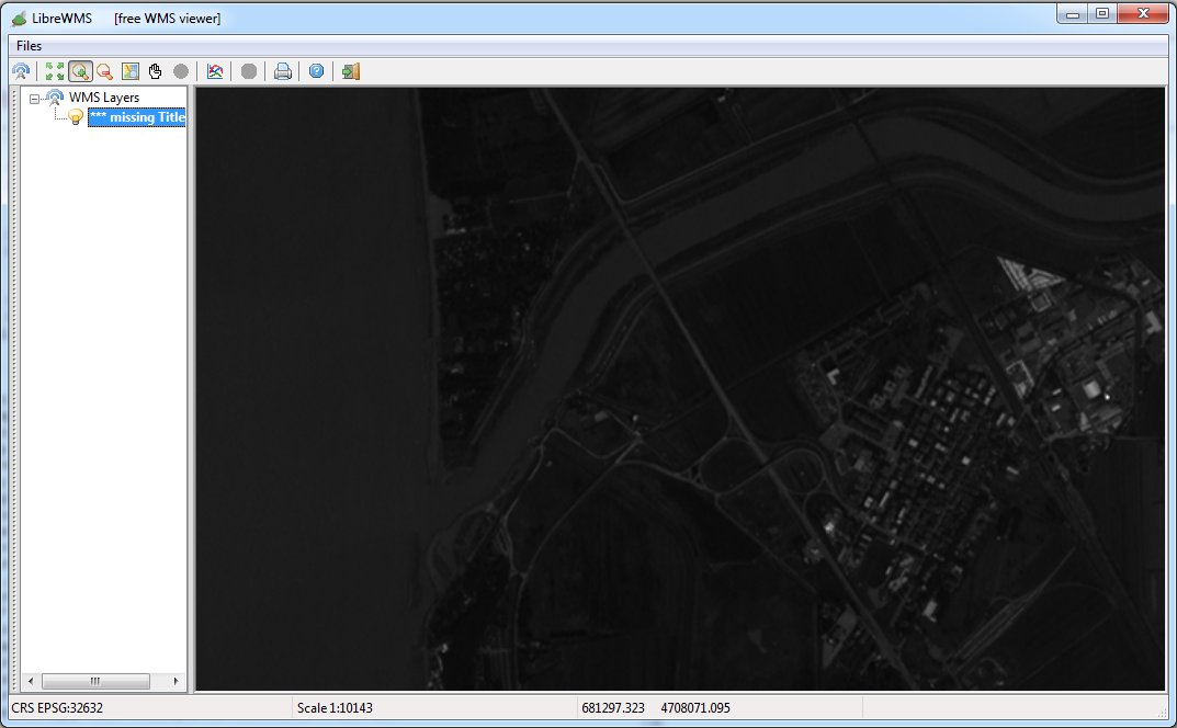
This first example corresponds to the default Style (no RasterSymbolizer at all): and in this case too, as we were expecting, it's a very unattractive image.
Please note: for any MULTIBAND Coverage the default style implicitly applied by RasterLite2 simply consist in selecting just the first band and then apply a basic, non-optimized Grayscale rendering.
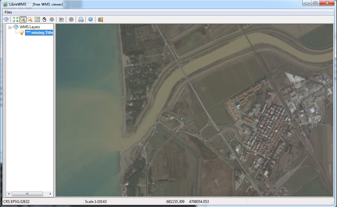
This second example represents a natural colors image (Red, Green, Blue); Contrast Enhancement corresponds to GammaValue by applying a 2.5 factor.
And in this case too we'll get a bright but very poorly contrasted image.
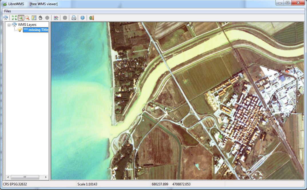
This third example represents a natural colors image (Red, Green, Blue); Contrast Enhancement corresponds to Histogram.
As we've already noticed in the Trieste case, this Contrast Enhancement method produces fairly good results, but not completely convincing.
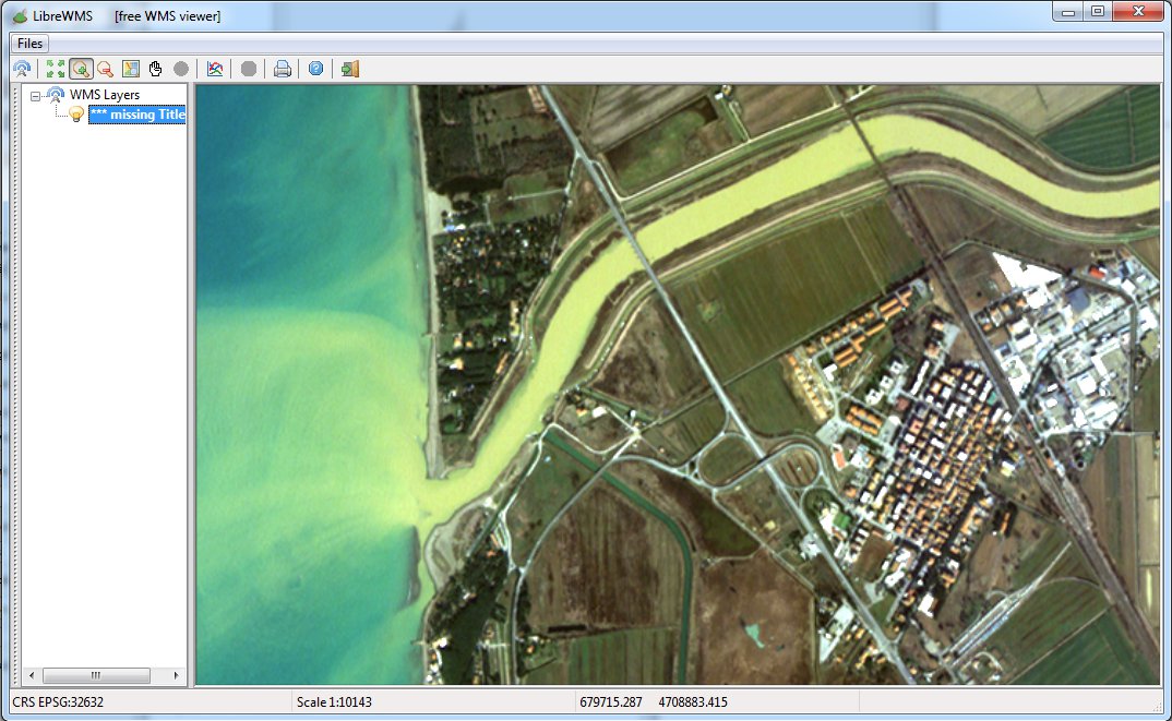
This fourth example represents a natural colors image (Red, Green, Blue); Contrast Enhancement corresponds to Normalize.
And even in the case of RGB images this Contrast Enhancement method confirms to be the best available option, because it usually produces naturally-looking images presenting a well balanced overall contrast.
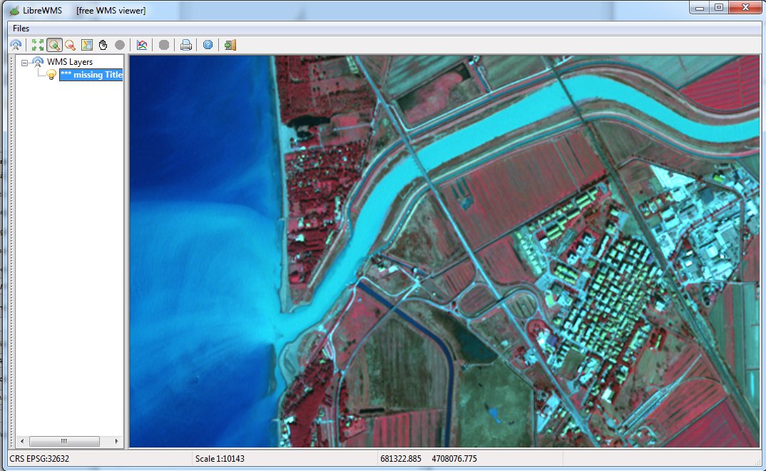
This fifth example represents a false colors image (Near Infrared, Red, Green); Contrast Enhancement corresponds to Normalize.
Please note: this image surely looks strongly unnatural and rather alien; anyway you could easily notice that it substantially facilitates photointerpretation, because all the vegetation is now clearly identified by many different shades or red.
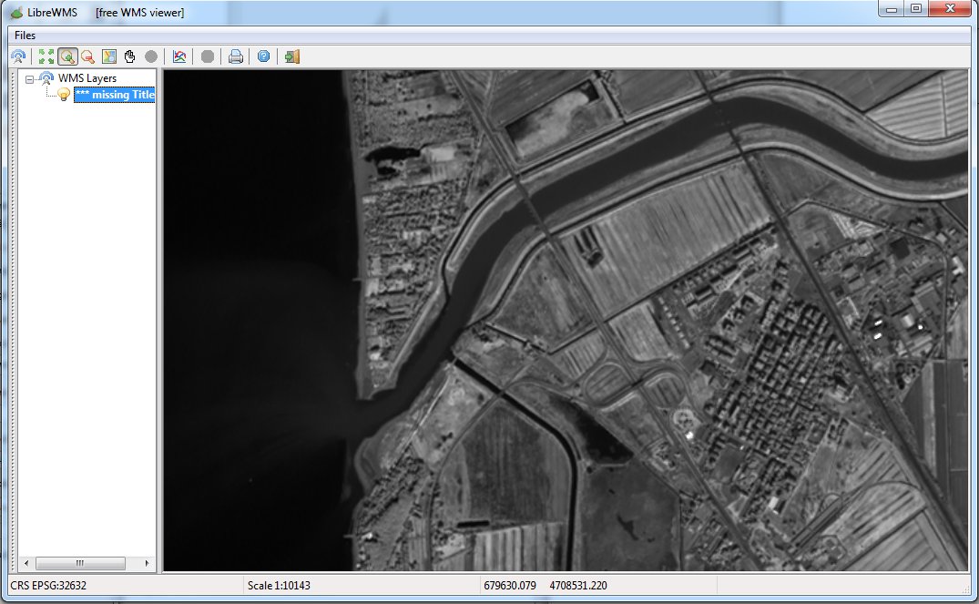
And finally this last examples shows a Grayscale image corresponding to the Near Infrared band alone and supporting the Normalize Contrast Enhancement method.
Back to RasterLite2 Tutorials index